Project Information
Site Location: Sohar, Oman
Equipment Name: Exhaust Blower
Service Performed: Vibration Analysis & Dynamic Balancing
Report Type: Case Study Report
Standard Referenced: ISO 20816
Prepared By: S. V. V. Krishna, Lead Engineer, Level -3 Vibration Analyst
Objective:-
The objective of this job is to reduce excessive vibration levels in the blower by performing dynamic balancing and to bring vibration within acceptable limits as per ISO 20816 standards.
Type of Balancing :-
- Balancing Method :- Dynamic Balancing
- Balancing Type :- Single Plane Balancing
Instruments Used:-
- Vibration Analyzer :- CSI 2140
- Tachometer
- Balancing Kit
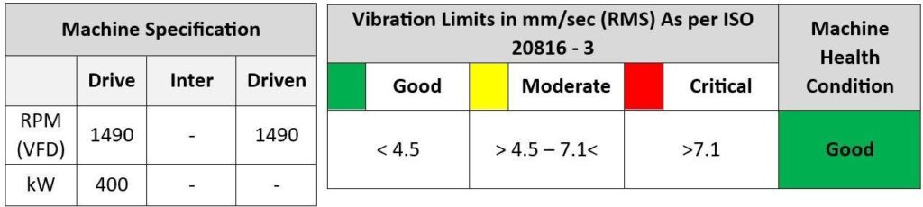
| Equipment Name | Motor Details | Fan Details | Health Status as forISO-20816-3 |
EXHAUST BLOWER (8490) |
Motor Details- 400 KW Motor Mechanical | Centrifugal Fan, Fan Mechanical | Critical limits– 7.1 mm/sec |
| Frequency: RPM1490(VFD) | Frequency: RPM1490(VFD) | Normal limits – 4.5 | |
| (24.8 HZ) | (24.8 HZ) | mm/sec |
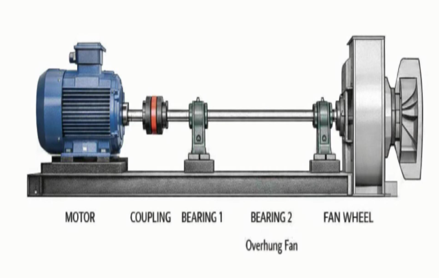
Fig: Schematic layout for vibration‑measuring points on a motor–fan assembly
Vibration Status as of 29 June 2025:
FFT SPECTRUM INTERPRETATIONS:
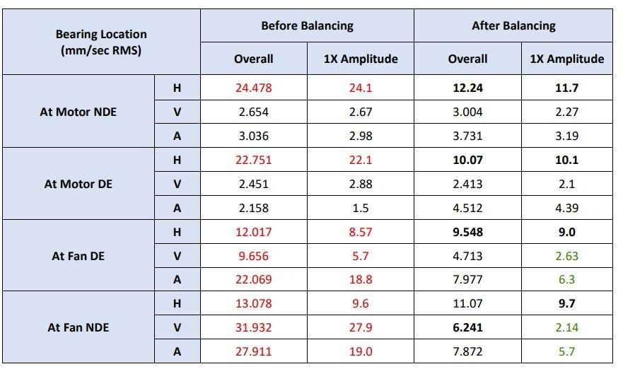
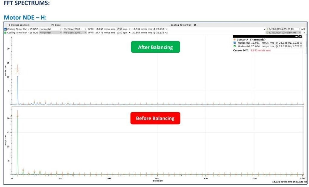
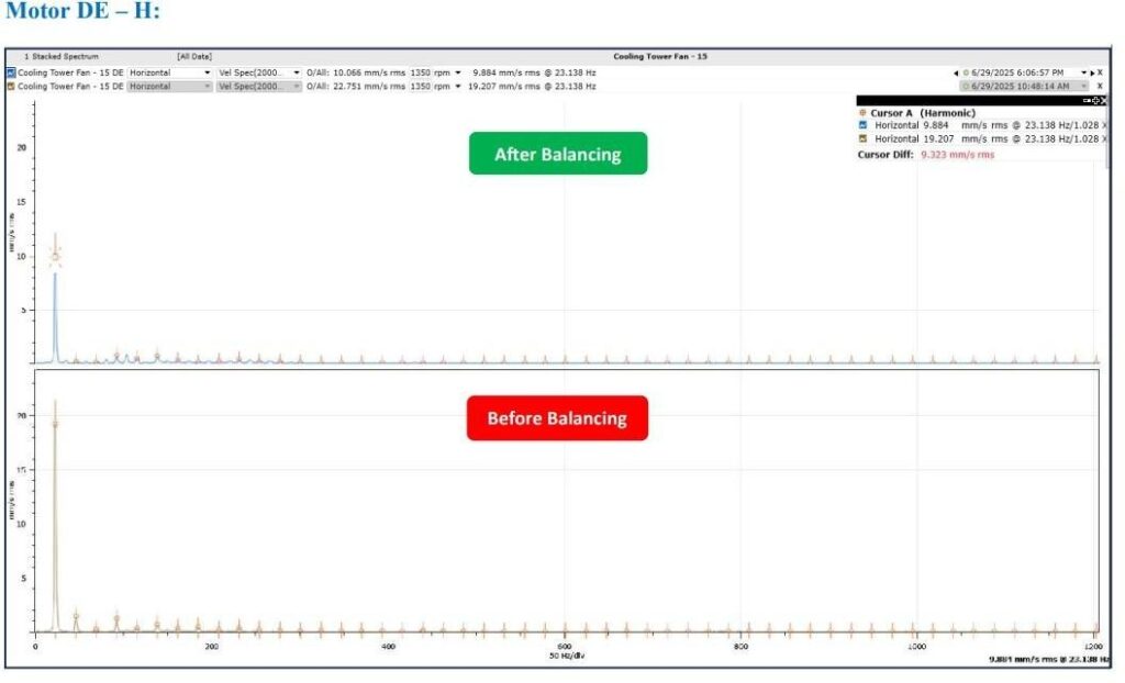
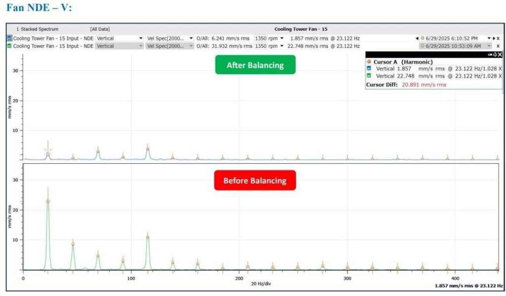
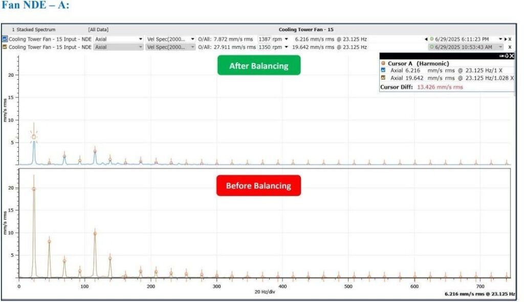
- Vibration on data collected on motor and fan bearings and the maximum casing vibration on amplitudes measured in the fan bearings were 22.06 mm/sec and 31.9 mm/sec respectively.
- The FFT spectrum of the motor bearings exhibiting significant amplitude of motor rotational frequency and fan bearings exhibiting dominant peak of 1X order of fan shaft running speed frequency (23.1 Hz) and its harmonics.
- To compensate for the unbalance force, added 206 grams on the fan impeller at 275 degrees from the reference point. After adding the weight, the overall vibration levels reduced from 22.06 mm/sec to
- 7.9 mm/sec on fan DE bearing and 31.93 mm/sec to 6.24 mm/sec on fan NDE bearing.
- After the balancing job, overall vibration on levels reduced however, the overall vibration on levels are above acceptable limits as per iso 20816-3.
- The velocity spectrum of motor bearings indicates significant amplitude of motor running frequency, which might be due to structural looseness.
- The FFT spectrum of fan bearings indicates significant amplitude of motor running frequency and its harmonics, which might be due to rotating looseness.
SUGGESTED ACTION PLANS:
- Replace the impeller with a new one at the next opportunity.
- It is recommendable to inspect the fan bearings for any increased bearing clearances, if found replace the same.
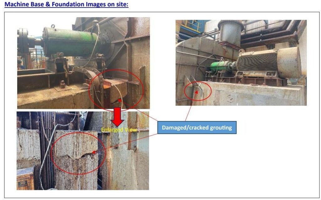
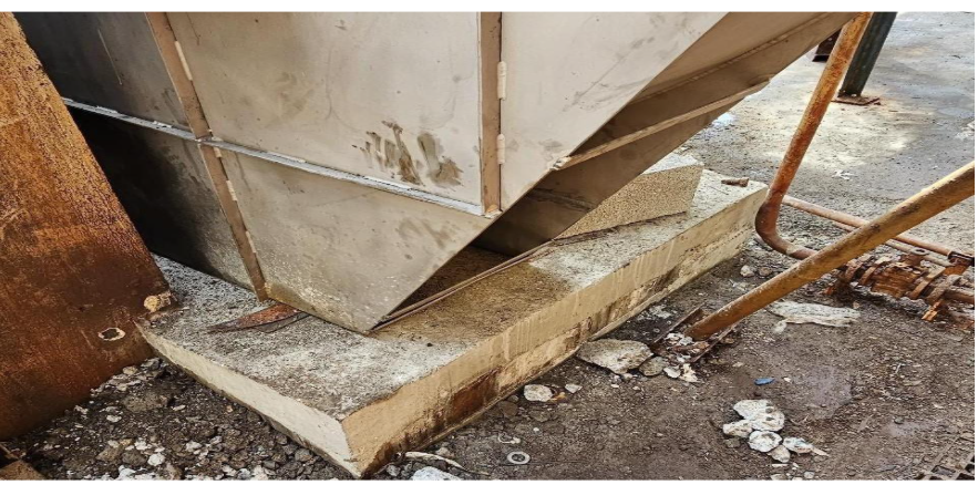
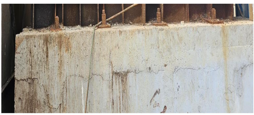
- Also, it is recommendable to replace the base grouting and replace the all corroded/rusted base bolts and retighten the all-fixing location with OEM recommended torque.
- Health status needs to be re-assessed after the above corrective maintenance action.
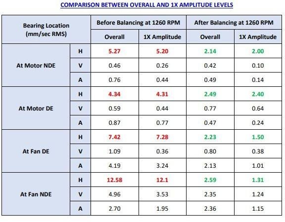
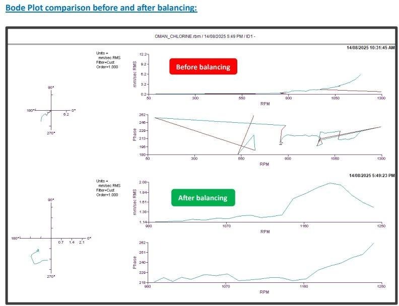
Vibration Measurement Results Before and After Balancing (Velocity in mm/sec)
During the initial inspection, high vibration levels were observed at the fan drive end (DE) and fan non-drive end (NDE) bearings, particularly in the horizontal direction.
COMPARISON BETWEEN OVERALL AND 1X AMPLITUDE LEVELS

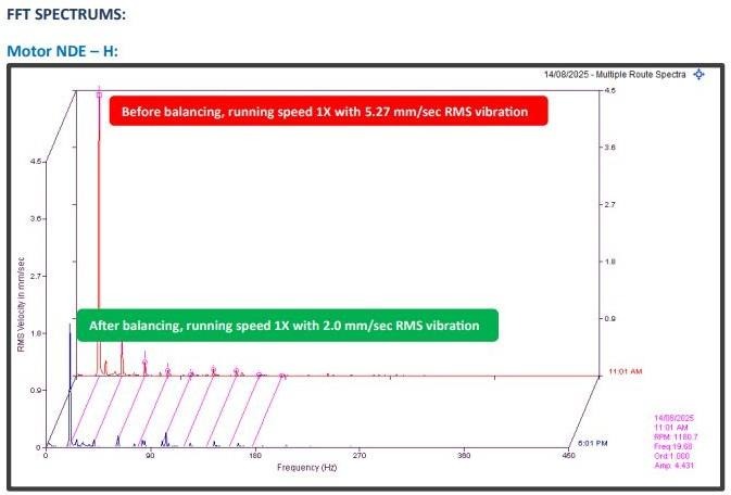
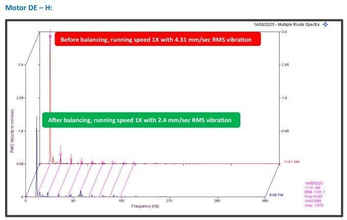
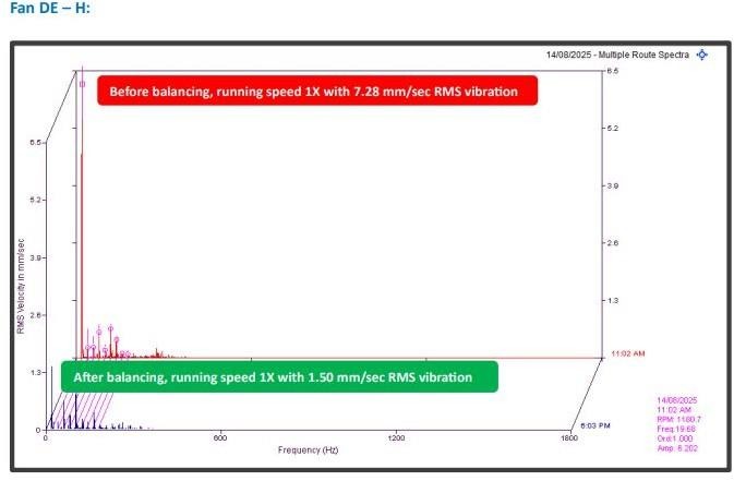
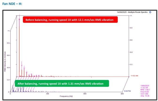
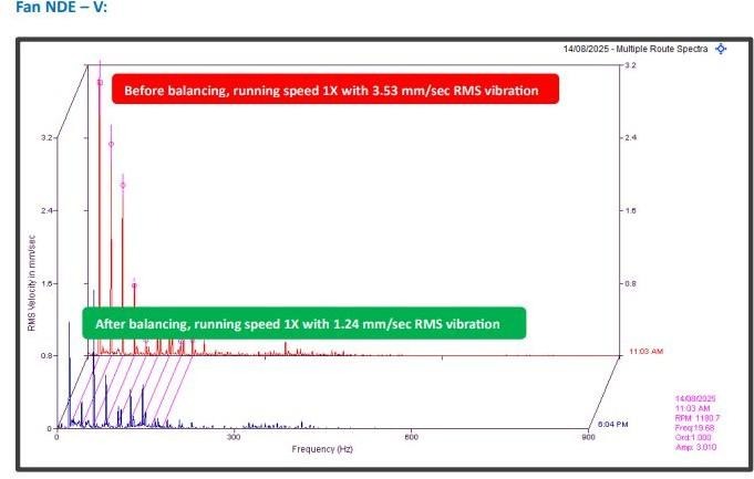
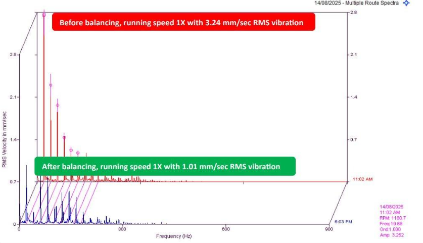
Vibration Status as of 14 August 2025:
FFT SPECTRUM INTERPRETATIONS:
- Vibration data were measured from motor and fan bearings, with the maximum vibration measured at 5.27 mm/sec on the motor NDE bearing and 12.58 mm/sec on the fan NDE bearing.
- The FFT spectrum of the motor bearings exhibits a dominant peak at the 1X order of the fan shaft running speed frequency (19.68 Hz), indicating unbalance symptoms which is confirmed by phase analysis.
- To compensate for the unbalance force, a total of 150 grams at 180 degrees from reference was added on the impeller. After adding the weight, the overall vibration levels reduced from 12.58 mm/sec to 2.59 mm/sec on the Fan NDE bearing and from 7.42 mm/sec to 2.23 mm/sec on the Fan DE bearing.
NOTE: Due to the increase in impeller diameter and cone, the fan can operate only up to a maximum speed of 1260 rpm with a maximum current of 450 A; hence, vibration data at the rated speed of 1490 rpm was not collected.
SUGGESTED ACTION PLANS:
- Present vibration data of the unit is within the acceptable limits as per ISO standards under load conditions. Therefore, the unit can be maintained in continuous operation.
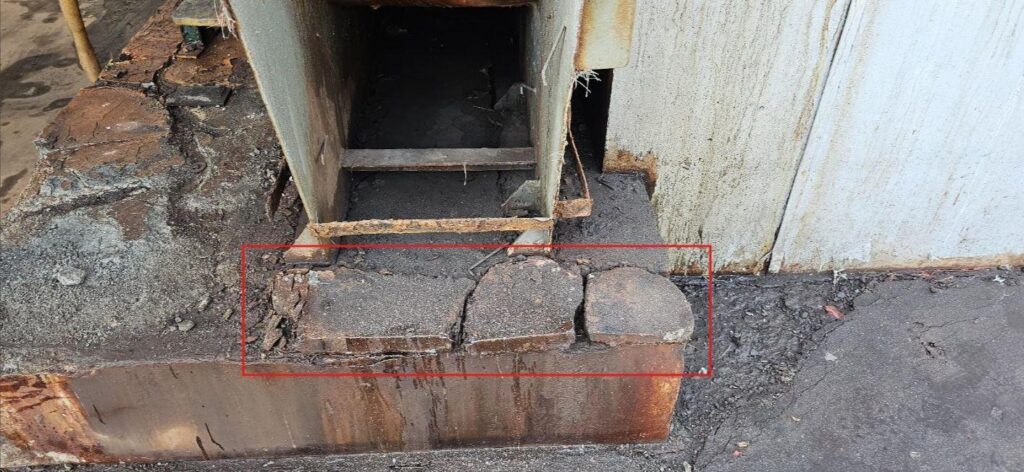
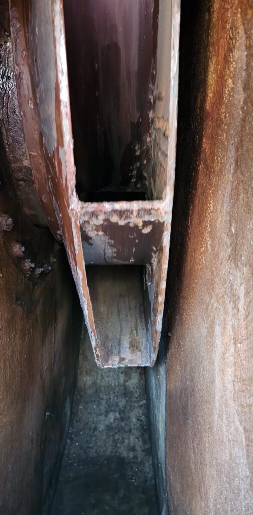
After modification Machine Base & Foundation
Images on site :
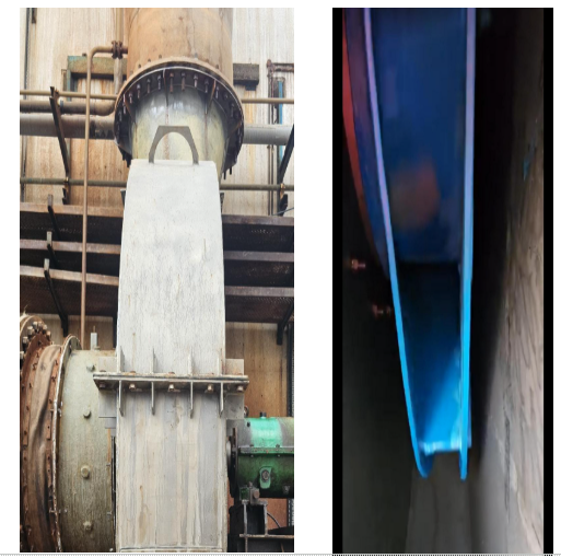
Fan casing replaced and impeller refurbished:
Conclusion:
The exhaust blower high vibration was caused primarily by rotor unbalance, as indicated by the dominant 1X frequency component. Dynamic balancing was performed successfully, substantially reducing vibration levels and restoring the equipment to normal operating condition in accordance with ISO 20816‑3.
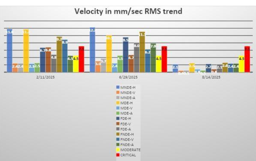
VELOCITY TREND :
| Overall Vibration Readings, Velocity, mm/sec-RMS | ||||
| S.No | Component | 11/02/2025 | 29/06/2025 | 14/08/2025 |
1 |
MNDE-H | 11.8 | 12.2 | 2.1 |
| MNDE-V | 2.4 | 3.0 | 0.4 | |
| MNDE-A | 2.4 | 3.7 | 0.5 | |
2 |
MDE-H | 11.7 | 10.1 | 2.5 |
| MDE-V | 2.3 | 2.4 | 0.8 | |
| MDE-A | 2.5 | 4.5 | 0.5 | |
3 |
FDE-H | 6.7 | 9.5 | 2.2 |
| FDE-V | 6.8 | 4.7 | 0.8 | |
| FDE-A | 4.8 | 8.0 | 2.1 | |
4 |
FNDE-H | 9.7 | 11.1 | 2.6 |
| FNDE-V | 8.9 | 6.2 | 2.4 | |
| FNDE-A | 4.5 | 7.9 | 2.4 | |
| MODERATE | 4.5 | 4.5 | 4.5 | |
| CRITICAL | 7.1 | 7.1 | 7.1 | |
TREND GRAPH:
Ensure Reliable Blower Performance with Ocean TMS Engineering in Oman
Excessive vibration can lead to unexpected breakdowns, reduced equipment life, and costly production losses. Ocean TMS Engineering specializes in Vibration Analysis, Dynamic Balancing, Condition Monitoring, Laser Shaft Alignment, Predictive Maintenance, and Machinery Diagnostics to help industries identify issues early and maintain optimal equipment performance.
Our ISO certified engineers use advanced diagnostic technologies to detect the root cause of vibration problems and implement effective corrective actions that improve reliability and reduce downtime. Whether you operate blowers, fans, pumps, motors, or other rotating equipment, Ocean TMS Engineering delivers proven solutions that keep your critical assets running efficiently.